The Storage of Potable Spirits in Tanks – AS1940-2017
Recent Developments
The storage and handling of flammable liquids of dangerous goods Class 3 & combustible liquids is regulated by AS1940. The 2017 version of this standard specifically included the storage and handling of potable alcohols in bulk having a strength of greater than 24% v/v alcohol. Prior to AS1940-2004 these liquids had not been dealt with and the requirement for storage was therefore unclear.
Appendix F of AS1940-2017 covers the traditional methods of storage as used by the wine and brandy industry up to 2004, covering installations which were in existence at that time. As set out in Appendix F, the level of performance is lower than the requirements set out within the main body of AS1940.
New installations should either comply with the full requirements of the body of the standard or a risk assessment should be carried out and the appropriate control measures adopted. Appendix E of AS1940-2017 provides risk assessment guidelines that should be considered when introducing, or increasing the volume of flammable or combustible liquid storages at a plant or facility.
Installations of potable spirits greater than 60% v/v or quantities greater than 60,000 litres are required to fully comply with the requirements of AS1940.
The following outlines the requirements of AS1940, Section 5 which deals with storage in static storage tanks, for installations which must comply with the body of the standard. Other sections of AS1940 are relevant to installations, however are not dealt with in this article.
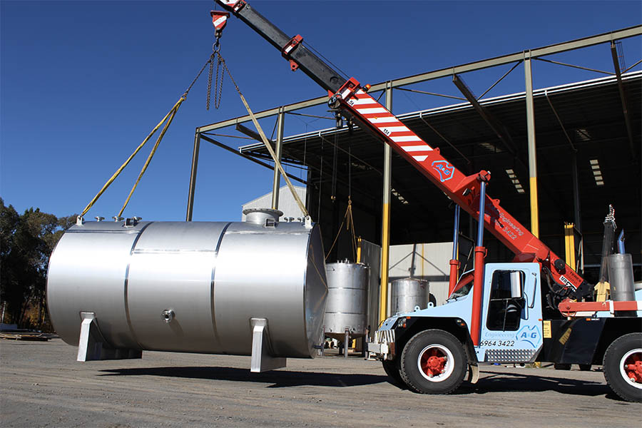
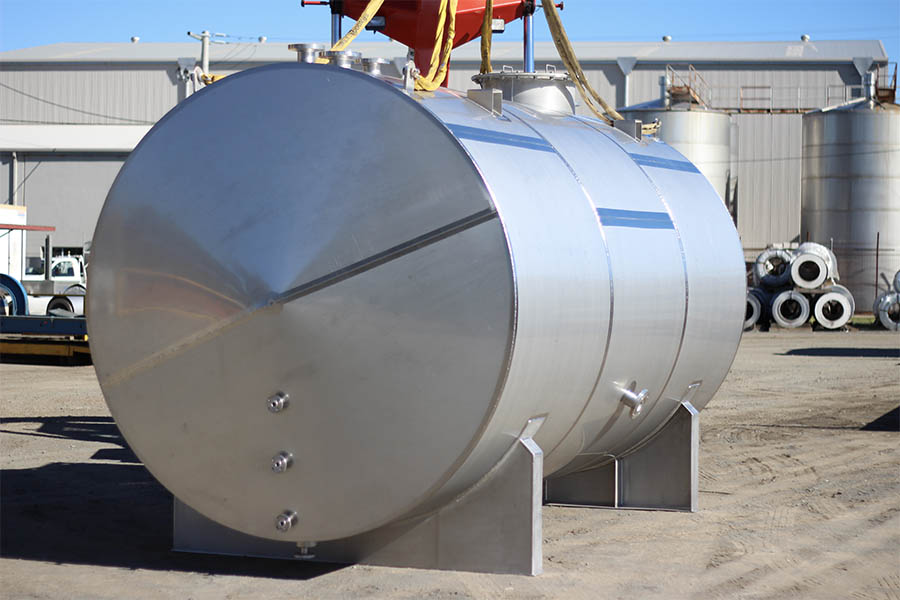
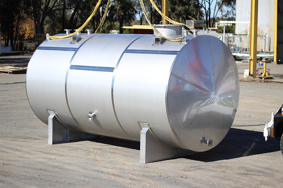
Tank Design & Manufacture
Tanks are to be manufactured to AS1692-2006, Steel Tanks for Flammable and Combustible Liquids. This sets minimum thicknesses for the tank depending upon the volume of the tank and whether it is to be a vertical or horizontal tank. It also sets the minimum requirements with regards to level indication, access, filling and emptying requirements, etc. Manufacture issues such as joints, welding and testing are also covered.
AS1692 also sets out the information which the purchaser must provide to the tank designer/manufacturer to enable the supply of a compliant tank.
Every fill pipe, suction pipe or dip pipe that enters the top of the tank and is likely to be opened to atmosphere at some time during normal filling is to be designed so that the lower end of the pipe is submerged by at least 25mm when the liquid level is at its lowest. If the fill pipe is direct from a process plant and is unlikely to be open to atmosphere in normal filling, this is therefore not required.
Liquid level indication and monitoring is dependent upon the contents of the tank, its size and the method of filling. The requirements are set out in AS1940 in detail.
The fill pipe is to discharge inside the tank at a level no greater than one pipe diameter above the bottom of the tank. Splash filling is not permitted. A pressure equalisation hole in the top of the fill pipe fitted with anti-flash gauze if the hole is greater than 1.5mm diameter.
A drain pipe and lockable valve should be fitted to the lowest point in the tank as far as possible from the draw-off pipe.
Any valve located below the liquid level of a category 4, 5 or 6 tank shall be fire safe.
Manholes shall be:
- Not less than 450mm diameter, preferably 600 mm diameter if personnel access is required.
- Fitted with a cover made from the same material and thickness as the tank shell and is to be liquid and vapour tight.
Each tank is to have a vent (either free vent or P/V vent) that allows the vapour space above the liquid to the vented to atmosphere.
Where fitted, the P/V vent is to limit the maximum pressure in the vapour space to 35kPa. The vacuum setting shall limit the minimum pressure to minus 0.5kPa (gauge).
Venting capacity is to be determined in accordance with AS1940 – 2017 Appendix H.
The discharge point of a free vent it to be higher that the filling point and at least 150mm above the top of the tank. It is to be designed to prevent ingress of foreign matter into the tank.
Emergency venting shall be provided for any above ground Category 3, 4 (Horizontal), 5 or 6 tank in flammable liquids service. The preferred design of the EV is the weighted-hinged type, although a manway with long bolts providing the same venting area as that of the manway opening is acceptable. Van EV shall also be supplied if the tank contains combustible liquid and is the same compound as a tank containing a flammable liquid.
Where both an EV and P/V vent are fitted, there should be sufficient difference between the pressure settings of the two vents to ensure that the EV opens only under emergency conditions when the normal venting provisions have been exceeded (nominally 7kPa differential).
A flame arrestor is to be fitted to the tank or vent pipe if the tank contains a flammable liquid the ullage space in the tank is within explosive limits.
Each tank is to be subjected to a leak test prior to painting. Hydrostatic testing is preferred but low pressure (not above 35kPa) air testing is also permitted.
The shell of the tank is to be metal stamped in a non structural area that the design complies with AS1692-2006, and a certificate is to be produced and supplied to the purchaser, stating the following:
- Manufacturer’s name
- Date of manufacture
- Materials of construction and type of coating applied, if any
- Test method and pressure
- Pressure/vacuum settings
- Maximum density of liquid to be stored
Tank Installation
AS1940 requires that all tanks are located within a bunded area large enough to contain the greater of 110% of the capacity of the largest tank or 25% of the total capacity of all want within the bund. An alternative to installation in a bunded area is to have a tank with secondary containment. This requires the manufacturing of a two tanks, one within the other, both of which must meet the requirements of AS1692.
Other additional requirements of self bunded tanks are:
- The outer tank shell volume is to be at least equal to the inner tank volume
- Means shall be provided to monitor the condition of the inner tank shell
- Physical protection is to be provided to prevent damage to the outer shell
- All piping connections to the tank shall be above the maximum liquid level
- Overfill protection is to be provided.
The distance between tanks within a bund is dependent upon its size, type and the contents.
All tanks in an installation must be marked so that the contents of the tank can easily be identified. Each tank must be individually identified. The markings on the tank must be at least 150mm high, be on the walls of the tank and easily read from the main access areas. Other information required on the tank include: Product name, e.g. Ethanol, dangerous goods Class Label, e.g. Class 3, Packaging Group (PG), e.g. PG II, Product U.N. number, e.g. 1170, Hazchem Code, e.g. 2 (Y) E and tank maximum volume.
If a tank is to be installed outside and a roof is erected over it to keep rainwater out of the bund the following requirements apply:
- Vents are to be above roof level.
- At least 2.5m clearance is to be provided between the top of the tank and the roof to permit personnel access if required.
- Adequate ventilation is to be ensured.
Piping and Valves
Piping, fittings and valves are to be constructed from materials compatible with and resistant to attack by the stored liquid. If pressure piping is used, it is to comply with AS4041. Materials are to be fire safe. All piping is to be identified with the direction of flow and product.
Flexible hoses are only permitted to be used at transfer points and where used their length is to be kept to a minimum.
Valves fitted below the liquid level of category 4 (horizontal tank up to 150kl), 5 Vertical tank up to 150kl) or 6 (vertical tank over 150kl) tanks containing flammable or combustible liquids are required to be fire safe. Valves must be able to be operated so that it is easily identified if it is open or closed. Detachable handles are to be avoided unless for security reasons. Handles are to be of at least the same material as the valve.
The tank fill point is to be;
- Identified with the product and tank number.
- Preferably at least 2m outside the building with ready access for the tank vehicle.
- At least 3m from any source of ignition.
Venting
Vent pipe work is to fall consistently back to the tank with a slope not less than 1:100. Joints are to be sealed and tested to 35kPa.
Interconnection of multiple tank vents is discouraged but if used, provision is to be made to prevent flashback or flame propagation from one tank to another via the vent piping.
A flame arrester or similar device is to be fitted to a flammable liquids tank, e.g. containing spirits or ethanol, where the vapour in the ullage space is within the explosive limits.
Location of the outlet of the vent is to be:
- At least 4m above ground level and 4m distant from any opening into a building.
- Clearly visible from the filling operators position.
- Higher than the tank vehicle.
Summary
This article is a condensed summary of criteria for storage of flammable liquids, including potable liquids with an alcoholic content over 60% v/v or in quantities over 60,000 litres. Issues such as locations of stores and tanks, filling and dispensing of tanks, electrical hazards, fire protection, emergency management and operational and personnel safety, including maintenance requirements have not been dealt with in this article, but are set out in detail within AS1940.
Readers should to obtain their own copy of the current standard, and where appropriate, obtain the advice of a specialist. This article should not be considered to be taken as professional advice as each installation must be designed to meet the specific circumstances.
A&G Engineering are experts in the design and manufacture tanks to AS1692 for your specific requirements.
Tom Mackerras
Engineering Manager
A&G


